I thought that I should give some background about our property. Where we started, what we've done and what we're working to.
It all began in December of 2005 when we bought our house. We found a house with just under 1 1/2 acres of land. We picked this house for several reasons. The house was big enough for all of our children, the kitchen was large enough to be able comfortably cook in, the house had lots of space between the other houses and it was far enough outside of the city to get some quiet and see the stars.
When we first bought our house the majority of the land was covered in weeds topping out at about 8 feet tall. We didn't think it would be to difficult to cut down and clear the weeds, boy were we wrong. It turns out that in the time the house was empty the land had been used as a dumping site. Piles and piles of trash had been dumped all over the property and covered in dirt. The weeds grew over the top of them and hid the piles of trash. So when I started cutting down the weeds let me tell you about my shock.
So the first thing was to cut down all weeds and find out just how much trash there was. Once we realized that we had about an acre covered with 3-4 foot tall trash piles it was time to get a trash dumpster. It took us almost a year having the dumpster emptied twice a week to finally remove all of the trash.
Once all of the trash was removed we found disease and termite ridden mesquite trees and bushes all over the property and smashed remnants of a fence. We eventually removed all of the trees over the course of several years to finally get down to clean soil. We're still, 7 years later removing pieces of glass and metal we find buried in the dirt, but we're finally to a point of building things up.
We built a fence around the property. I built the fence using reclaimed steel fence posts for the upright posts and 1/2 rebar for the top rail. I did this because I was able to buy the reclaimed posts for $3.00 US a piece instead of $9.00 US a piece. Plus by using the rebar for the top rail I was able to buy 20 feet for $5.00 US instead of the top rail tubing for $13.00 US per 10 foot section. This all added up to a huge cost saving for us. I welded the top rails together and the rails to the top of the posts. By welding it all I did away with the extra cost for all the extra connectors. I also built all of the gates from scratch instead of buying prebuilt gates. By doing all of this ourselves it cost us about $1,500.00 US for the entire fence. This was a significant savings over the $12,000.00 quotes I got from the fence companies. If you check salvage yards you can get great deals.
We also dug ditches and laid out irrigation lines around the perimeter of the front half of the property. I used the irrigation to water the trees I planted. I planted 11 pine trees, 2 mulberry trees, 2 apricot trees, 2 peach trees, 3 apple trees, 2 plum trees, 1 grapefruit tree, 1 lemon tree and 3 orange trees. Here in the Arizona desert the underground irrigation works really well for the trees and saves lots of water. We still have the back length of the fence line to plant with trees and put in irrigation.
We've also begun working on digging an underground cistern. The plan for the cistern is to use it as a rainwater and gray water collection system. I plan on re-plumbing the sinks, tubes and showers so the gray water is diverted to the cistern. Then pressurize the water to use for the irrigation and toilet tanks. This would allow us to use the water that we pay for twice and use less water. Once the cistern is completed I'm going to build a green house and my garden oven the top of it.
We're in the process of building our outdoor earth kitchen. The entire kitchen design is based around wood fired cooking. Since wood fired cooking is carbon neutral and just tastes so good this is my preferred cooking method. This outdoor kitchen also allows us to cook in the summer heat without adding more heat into the house. I dedicated my blog Earth Kitchen Project to the chronicling of building the outdoor kitchen.
I plan on building a chicken coop and smoke house in the back of the property as well as a shed and root cellar. I also have plans to build a workshop to give me a place to setup my tools permanently and work on my blacksmithing.
My plans also include building and installing alternative energy systems. I want to have a solar water heater, solar and wind power generators. I want to build a solar heating system for the hot tub. Maybe even research a viable alternative cooling system for the house. We also might build an outdoor shower and maybe even a small guest house. Overall our plans are to be as self sufficient as possible. I will continue posting pictures and information on all of our projects so that we may help in answering peoples questions or maybe even inspire them to try some of this on their own.
Friday, February 8, 2013
Saturday, February 2, 2013
Earth Kitchen Project,,,My Outdoor Kitchen
The Earth Kitchen Project was the first blog I started and was my first at getting my hands dirty with cob and adobe building. If you are at all interested in wood fired ovens or my adventure in building an outdoor kitchen area out of cob and adobe the please feel free to read the blog at earthkitchenproject.com. The earth kitchen project blog is specifically focused on building my outdoor kitchen.

This is the the first part of my outdoor kitchen almost completed. This is my large oven. It's a wood fired oven that cooks pizza, breads, roasts, vegetables and more beautifully. The inside open space of the oven is 48 inches in diameter and 27 inches tall. It's a big oven and I love it.
I have so much information about building the oven as well as plans for the rest of the kitchen that I put all the information into 1 blog, the earthkichenproject.com. So feel free to enjoy that blog as well. I hope it can help and maybe inspire you to build something of your own.
I have so much information about building the oven as well as plans for the rest of the kitchen that I put all the information into 1 blog, the earthkichenproject.com. So feel free to enjoy that blog as well. I hope it can help and maybe inspire you to build something of your own.
Friday, February 1, 2013
Home Built Forge 2.0
I am still very proud of my boys for building the large forge as their summer project. It was the first post I put on this blog. I did however run into an issue with the forge, it's a fuel hog. I figure that if you had 4 or more people all needing a forge at the same time the large forge is awesome but, unless you're working on something big the forge turns out to be too large for just 1 person. So a new project was born, to design and build a smaller more fuel efficient and more versatile forge. I again did some scrounging for materials and came up with what I think is a good design.
So I based my design on the brake drum ideas that are popular online. However I felt that the normal brake drum forges where too shallow so I got 2 matching drums and welded the open ends together. I then cut the top off to make a nice deep fire pot. I used some rebar for handles and supports and tubing for legs and tuyere. I also added an ash dump to this design.
 First thing that you notice is the handles. I made them taller and centered so that I can use a rod, pipe or anything through the handles to remove the lid or place the lid on while the forge is hot without being burnt. You'll also notice the tabs coming down from the lid. These lock into the ridges and keep the lid stable.
I wanted my fire pot to be removable for cleaning or any needed repairs. So to do this I welded small stubs of 1/2 inch rebar to the old rim to match the bolt hole pattern in the bottom of the fire pot. This allows the fire pot to easily be removed but, keeps it study for operation. The fire pot also holds down my diffuser plate. That way if it ever gets damaged it can simply be removed and replaced at a later date without having to rebuild anything.
I added the ring of rebar to act as a handle be able to move the forge when needed, to act as a buffer to help keep anyone from getting burnt and to give me a place to hang s few tools to tend the fire. The ring could also act a s a base for a support if I ever needed to add one.
 Here you can see that I made a fairly deep fire pot in order to get some good controlled heats while at the same time attempting to conserve fuel. Both the large forge and this small forge were built with the idea of using wood and charcoal as fuel but, from what I've been told coal or coke could be used as well. I don't know of any coal suppliers near me in the middle of the Arizona desert but, we have lots of mesquite hard wood. I cook with mesquite cuttings all year long and always have some on hand.
I also did some research and found out that the EPA allows you to burn used oil and wood scraps form construction sites to pallets as a fuel source in forges, heaters, boilers, foundries and more. According to the EPA this is allowed, legal and considered recycling because none of it ends up in landfills and since it's considered waste the EPA sees it as using that energy for another purpose with little to no waste product left.
 You can see here that I made 2 removable cutouts. I bent some rebar to match the curve of the fire pot to attach to the cutouts. Then I added 2 upright bars connected to the fire pot at an angle so the cutouts could be removed when needed.
My idea here was to be able to remove either side as needed or for longer work I could remove both cutouts in order to heat small sections at a time.
The nice thing about this design is the flexibility. This allows me to use a relatively small forge for many things and since the smaller forge is more fuel efficient I can conserve fuel, which is always a good thing.
 Here is a picture with the cutouts removed and the top on. I plan on using this option for anything that needs concentrated heat like the forge welding of pattern steel.
Also I left the bolt and axle holes open in the top. I wanted use the top to get a chimney effect but, not blow all the heat out of the cutout openings.
I also had planned to use the cutouts in place and the top on when I was finished in order to help extinguish the fuel rather that just burn everything out every time.
Just a note on the fire pot. As you can see from this picture I did not try to completely weld the seem of the 2 brake drums. I was afraid that if I did then the weld may crack during a heating or cooling cycle. Once a crack starts it will run the entire length of the entire weld. So by only welding short beads if one cracks I don't have to worry about the entire upper half of the fire pot suddenly coming apart from a crack that occurred during a heating or cooling cycle. This would be very bad to have happen while the forge was being fired. So I thought it would be a good idea to try and avoid that and not make a continuous weld.
 I added an ash dump on this forge. The angle iron that I used wasn't wide enough so I had to add short triangular pieces to each side to make the closer wide enough to seal the bottom of the tuyere pipe. I just used 2 oversized nuts for the hinge point welded to 2 small steel plates to provide enough space for the pivot. I used a nut and bolt or the pivot pin and welded the angle iron to the pivot pin. I lined up the angle iron and the bottom of the tuyere to get a good seal and welded the steel plates to the tuyere.
I also decided to weld on some counter weight to the end of the angle iron to counter act the force of the air coming in through the tuyere. Depending on the force of the air that I need to use I ma have to add a little more counter weight.
Once I use the forge for a little while and I make sure everything is working right I'll give it a coat of black heat resistant paint to clean it up.
I also wanted to say that all of the material I used foe this forge was also scrounged for free so there was no cost for any of these materials.
The only other thing that I may end up doing is to add some clay and sand refractory around the base or the fire pot inside the old rim to help reflect the hat back to the fire pot instead of radiating out. I'll use the forge and test it out first to see if I need to add it or not.
I hope this has helped answer some questions or maybe given you some ideas.
So I based my design on the brake drum ideas that are popular online. However I felt that the normal brake drum forges where too shallow so I got 2 matching drums and welded the open ends together. I then cut the top off to make a nice deep fire pot. I used some rebar for handles and supports and tubing for legs and tuyere. I also added an ash dump to this design.
I wanted my fire pot to be removable for cleaning or any needed repairs. So to do this I welded small stubs of 1/2 inch rebar to the old rim to match the bolt hole pattern in the bottom of the fire pot. This allows the fire pot to easily be removed but, keeps it study for operation. The fire pot also holds down my diffuser plate. That way if it ever gets damaged it can simply be removed and replaced at a later date without having to rebuild anything.
I added the ring of rebar to act as a handle be able to move the forge when needed, to act as a buffer to help keep anyone from getting burnt and to give me a place to hang s few tools to tend the fire. The ring could also act a s a base for a support if I ever needed to add one.
I also did some research and found out that the EPA allows you to burn used oil and wood scraps form construction sites to pallets as a fuel source in forges, heaters, boilers, foundries and more. According to the EPA this is allowed, legal and considered recycling because none of it ends up in landfills and since it's considered waste the EPA sees it as using that energy for another purpose with little to no waste product left.
My idea here was to be able to remove either side as needed or for longer work I could remove both cutouts in order to heat small sections at a time.
The nice thing about this design is the flexibility. This allows me to use a relatively small forge for many things and since the smaller forge is more fuel efficient I can conserve fuel, which is always a good thing.
Also I left the bolt and axle holes open in the top. I wanted use the top to get a chimney effect but, not blow all the heat out of the cutout openings.
I also had planned to use the cutouts in place and the top on when I was finished in order to help extinguish the fuel rather that just burn everything out every time.
Just a note on the fire pot. As you can see from this picture I did not try to completely weld the seem of the 2 brake drums. I was afraid that if I did then the weld may crack during a heating or cooling cycle. Once a crack starts it will run the entire length of the entire weld. So by only welding short beads if one cracks I don't have to worry about the entire upper half of the fire pot suddenly coming apart from a crack that occurred during a heating or cooling cycle. This would be very bad to have happen while the forge was being fired. So I thought it would be a good idea to try and avoid that and not make a continuous weld.
I also decided to weld on some counter weight to the end of the angle iron to counter act the force of the air coming in through the tuyere. Depending on the force of the air that I need to use I ma have to add a little more counter weight.
Once I use the forge for a little while and I make sure everything is working right I'll give it a coat of black heat resistant paint to clean it up.
I also wanted to say that all of the material I used foe this forge was also scrounged for free so there was no cost for any of these materials.
The only other thing that I may end up doing is to add some clay and sand refractory around the base or the fire pot inside the old rim to help reflect the hat back to the fire pot instead of radiating out. I'll use the forge and test it out first to see if I need to add it or not.
I hope this has helped answer some questions or maybe given you some ideas.
Thursday, January 31, 2013
My Flag Pole . . . Third Time Is The Charm
Ok if you read my post about my antenna tower than you know about the storms that we get here in the Arizona desert. If you haven't read the post then I'll give quick explanation. We have severe wind storms, sand storms and monsoon storms. Since we have lived here at least twice the winds have reached speeds of 125 miles per hour. This tends to damage things sticking up in the air.


After we bought our house I had to take out the tree in the middle of the circular driveway. I turned out to be diseased ad there was nothing that we could do for it. So I suddenly had this hole and I had the perfect place for a flag pole. I wanted to put one up on the property somewhere anyways so I thought this worked out perfect. I went out and started flag pole shopping. I found an aluminum segmented pole that was rated for 125 mile per hour winds. It was 20 foot tall and came with a 2 foot sleeve to concrete into the ground in order to mount the pole into. So I concreted the sleeve in the ground and installed the pole. It was a nice 18 foot pole and everything was good. Well we had a storm and the winds hit 75 miles per hour (which was 50 miles per hour less than it was rated) and the flag pole bent severely. I called the company and they sent me replacement segments and suggested that I add a raised concrete pedestal to the pole and add cement inside the bottom section or two of the pole. So this is what I did but, when we had the storm that took out the antenna mast the last time with winds hitting 125 miles an hour the flag pole was just snapped off like small tree. My son and I were outside tying things down when we heard this loud crack and the flag pole came crashing down. So scratch flag pole number 2.
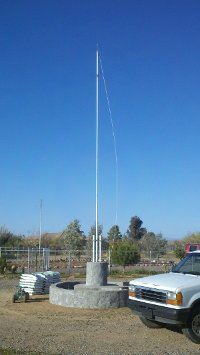
After a couple of years with my broken flag pole just sitting there we inherited a flag pole from my in laws since the were moving. This was a nice and heavy overbuilt steel flag pole. We also got a lot of blocks, pavers, stepping stones, edging, brick and more. Not a lot of any one thing but, a lot in total. So I decided that I couldn't possibly leave the pole on the ground so here come flag pole number 3.
I figured that if I was going to build flag pole number 3 that I wanted it to be solid without a worry of it coming down like the previous 2 poles. I also had always planned for an herb garden around the flag pole and I had already ran and irrigation line so I figured now was the time to put it in.
So I started with the existing pedestal and added 2 up right stabilizing supports and I welded support braces to the up rights and wrapped flat steel under tension to lock the up rights in place. I also added anchors to lock everything inside the concrete. On top of the pedestal in between the uprights I welded a support system for the mounting plate that I made. I also measured and spaced out the blocks for the herb garden.
Once that was done I measured and stacked up the blocks to make the stairs and setup a form for the concrete base.
Before I started filling the form with concrete I started filling some inner space with the broken pavers, bricks and edging. I also added more as I was putting in more concrete. I wanted to use what I had so I could add weight and structure without having to buy more concrete. I then setup the form for the larger pedestal to concrete the rest of the support and anchors for the up rights. My form was a little short so I had to concrete most of the pedestal then come back the next day and move the form to finish.
Next I dug and leveled a small trench for the first course of blocks for the herb garden. Then I stacked the next 2 courses and tweaked them to smooth out the circle. Next I cut up some old T-posts and hammered them down inside each hole in the blocks except for the 8 holes where I plan to put my solar lights. I used 1/2 inch rebar for those holes. The rebar was measured so that I had plenty of length to mount the solar lights on.
After I removed all of the forms I started mixing earthen concrete. That's a mixture of clay subsoil with the concrete. It takes longer to dry but, dries as hard as concrete and is a more green solution than straight concrete. The trick that I learned was not to add more the 45% by volume of the clay to the concrete. This works great for the fill and locked the wall together great but, I haven't tried to use the earthen mix with anything that was load bearing. I've read that you can but, I've had yet o try it.
Then I used the earthen mix to fill in all the gaps and start to smooth out the sides and top of the wall and stairs. I also used it inside of the wall if there was any gaps and to close up and on the bottom sides of the stairs to fill everything in and shore things up.
Next I mixed and applied stucco to the outside wall and pedestal and smoothed out the stairs, base and top of the pedestal. I had some fun with the stucco since I like the rough finish rather than a very smooth finish. It took me a few days to get it all done.
I finally got all of the stucco on and leveled out. I also had to come back a couple of times to fill in the cracks that developed. I also had to come back and fill in and the front and sides of the bottom step.
So with the stucco done it was time to put up the flag pole in order to mark and fit the cross member / pivot that I designed in to the flag pole. The purpose of the cross member is to act as a stiffening support so that stress on the pole gets transferred through the up rights as well as the bottom of the pole. The second purpose for the bar is as a pivot. I did this so if anything has to be repaired the pole can be lowered and raised again without having to lift it by hand like we did for the fitting of the bar. All I can say is that I'm proud of my boys, since it took 3 of them working with me to get the pole up and in place. Then it took all 4 of us to take the pole back down so I could finish up the work on the pole, get it painted and install the weather vain.
Next I welded 2 short pipes on the on the pole over the holes I made for the cross member bar. I did this to add strength around the holes and give the pivot point more strength. After cleaning up the welds and making finishing the holes on the butt plate I sanded then primered the pole with a self etching primer then painted the pole with a gloss white paint. Then I installed and adjusted the weather vain. Next I added the pulley at the top of the pole and the cleat at the bottom of the pole. Once the rope was added the pole was ready to mount.
My boys helped me again to mount the the pole. Once the pole was mounted I added the clips to the rope so I could test hang the flags. While the pole was down I also primered and painted the cross member bar, uprights and exposed mounting plate.
Next I painted the exposed surfaces. However I didn't want to use regular paint so I made some lime wash and added some solid colorant like what is used for colored cement. I mixed it well and painted it on. I applied 2 coats over everything and a few spots needed 3 coats. I used the lime wash because once it bonds with the cement the color is permanent and does not rub off. If any cracks develop they can be filled with some lime putty and painted over with another coat of the colored lime wash and everything will continue to bond together and get stronger over time without chemicals or solvents.
The last things were to add the weed barrier, run the irrigation to manifolds for the soaker lines, back fill with a composted growing soil, and plant some herbs. I also installed my solar lights. I'm happy with how this came out. Since we finished building this flag pole and planter it has weathered several extreme storms without any issue.
I also forgot to point out that the pivot is designed to lower the pole towards the front gate opening as you can see from this picture. This was done to make it easier to clear everything when it is necessary to lower it down.
Just a quick not about the planter. This has been wonderful and extremely productive all year round and really adds to the aesthetic appeal of the flag pole. I cook with the herbs, onions, leaks and garlic from this planter almost daily. It's been wonderful.
No More Antenna Problems
I thought I would post this just in case other people have had similar problems or maybe give someone an idea.
First off let me explain why I'm using an antenna. Where we live we can't get cable and satellite tv is just ridiculously expense so we opt to use an antenna for basic over the air broadcasts. Since that and netflix are our only entertainment we do try to keep it up and working.
Ok all about why and how we built the tower. Here in the Arizona desert we get lots of high wind storms. Most of the time it's ok but, at least once a year we get a nasty one with extremely high winds that always seems to damage something. In my case the antenna mast was damaged every year and twice one year. So in the first 3 years of owning our house the antenna mast was damaged 4 times. Well let me tell you that is a real pain in the butt to have to keep fixing. So when the mast was damaged a 5th time I said enough was enough and starting looking into how to never have this problem again. The answer I came up with was a nice sturdy radio tower. The way the radio towers are built the are very sturdy and hold up to the wind well.
First thing I did was to start looking for used towers but, the cheap ones were $75-$100 dollars US per 10 foot section. Well that wasn't going to work for me. So back to the drawing board. So I looked at the antenna mast and found that it was a single thin walled pipe. in doing some comparisons I found that I could get a slightly larger diameter and thicker walled galvanized pipe in 10 foot 6 inch section from my local Home Depot. I also found 20 foot long 1/2 thick rebar cheap there are well. So I suddenly had the idea to build my own radio tower. I did some quick math and figured I would need 10 pipes and 5 pieces of rebar.
 I cut the rebar into 1 foot segments then measured out and marked the locations were all of the rebar went. I then used 3 pipes to make 1 10 foot section. I repeated the 2 more time to make 3 sections total.
On the top section I added a mast to be able to mount the antenna on. I made sure that the mast was solid and well supported to avoid as much vibration as possible.
Once all three sections were completed we lined them up and slipped the ends of one into the ends of the other pipe sections. Each pipe had a 6 inch section that was pressed down to fit inside the other end of the pipe. This worked out really well. We put them together, leveled them out and welded them. I decided the I didn't want them to come apart in order to give the tower a little more rigidity.
Once all of the sections were leveled and welded we we were ready to put the tower up. At this point I had to get 4 more pipes to make the braces I used to mount and stabilize the tower to the house. I also bought 8 bags of concrete for the base foundation.
We dug the foundation hole 3 feet deep and 3 feet in diameter. My boys and a friend all helped to pick up and move the tower and place the end into the foundation hole.
 The 5 of us then started to walk the tower up. This was a bit of a challenge but, we got it standing. Once the tower was up we gad to put the braces in place. I had to have the boys move the welder onto the roof so that I could weld the braces on to the tower after mounting them to the house.
We then took some broken pieces of concrete and placed them in the hole and ran some rebar in the hole to add an extra anchor. We then poured in the concrete and added some more broken concrete. Then troweled the top so the center was raised to expel any water. We also had the boys put their hand prints and the year in.
After letting the concrete set I installed the antenna on top and then ran conduit along one of the braces for electrical wiring and mounted a light about 20 feet up.
In total the tip of the tower now sits at 32 feet. This allowed me to now mount the antenna at about 31 feet. Which was about 16 feet higher than the old mast. This new height has really improved our reception and the amount of channels that we receive.
You can see one of my sons in the second picture having climbed almost to the top of the tower. It is very stable and hardly shakes or moves. About 2 months after the tower went up we had a storm with gust pushing 125 miles per hour and the tower held like a champ. However the winds snapped my flagpole in the front yard like it was a twig. Since the installation of the tower it has held without issue with every sand storm, wind storm and monsoon.
The one thing that I should note is that I did ground the tower. I put in an 8 foot grounding stake several feet away and ran 4 heavy 6 gauge wires from the tower to the grounding stake. I also ran a separate ground from the coaxial cable connector down to the grounding stake as well just as an extra precaution.
All in all I spent about $100 US to build the tower. If you ask me it was money well spent given that I don't have to fix it anymore, we get better reception and more channels. The lights works well enough to light up the east side of our property. I have also thought about the possibility of mounting wind mills on a tower like this. We'll just have to see what other people come up with.
First off let me explain why I'm using an antenna. Where we live we can't get cable and satellite tv is just ridiculously expense so we opt to use an antenna for basic over the air broadcasts. Since that and netflix are our only entertainment we do try to keep it up and working.
Ok all about why and how we built the tower. Here in the Arizona desert we get lots of high wind storms. Most of the time it's ok but, at least once a year we get a nasty one with extremely high winds that always seems to damage something. In my case the antenna mast was damaged every year and twice one year. So in the first 3 years of owning our house the antenna mast was damaged 4 times. Well let me tell you that is a real pain in the butt to have to keep fixing. So when the mast was damaged a 5th time I said enough was enough and starting looking into how to never have this problem again. The answer I came up with was a nice sturdy radio tower. The way the radio towers are built the are very sturdy and hold up to the wind well.
First thing I did was to start looking for used towers but, the cheap ones were $75-$100 dollars US per 10 foot section. Well that wasn't going to work for me. So back to the drawing board. So I looked at the antenna mast and found that it was a single thin walled pipe. in doing some comparisons I found that I could get a slightly larger diameter and thicker walled galvanized pipe in 10 foot 6 inch section from my local Home Depot. I also found 20 foot long 1/2 thick rebar cheap there are well. So I suddenly had the idea to build my own radio tower. I did some quick math and figured I would need 10 pipes and 5 pieces of rebar.
On the top section I added a mast to be able to mount the antenna on. I made sure that the mast was solid and well supported to avoid as much vibration as possible.
Once all three sections were completed we lined them up and slipped the ends of one into the ends of the other pipe sections. Each pipe had a 6 inch section that was pressed down to fit inside the other end of the pipe. This worked out really well. We put them together, leveled them out and welded them. I decided the I didn't want them to come apart in order to give the tower a little more rigidity.
Once all of the sections were leveled and welded we we were ready to put the tower up. At this point I had to get 4 more pipes to make the braces I used to mount and stabilize the tower to the house. I also bought 8 bags of concrete for the base foundation.
We dug the foundation hole 3 feet deep and 3 feet in diameter. My boys and a friend all helped to pick up and move the tower and place the end into the foundation hole.
The 5 of us then started to walk the tower up. This was a bit of a challenge but, we got it standing. Once the tower was up we gad to put the braces in place. I had to have the boys move the welder onto the roof so that I could weld the braces on to the tower after mounting them to the house.We then took some broken pieces of concrete and placed them in the hole and ran some rebar in the hole to add an extra anchor. We then poured in the concrete and added some more broken concrete. Then troweled the top so the center was raised to expel any water. We also had the boys put their hand prints and the year in.
After letting the concrete set I installed the antenna on top and then ran conduit along one of the braces for electrical wiring and mounted a light about 20 feet up.
In total the tip of the tower now sits at 32 feet. This allowed me to now mount the antenna at about 31 feet. Which was about 16 feet higher than the old mast. This new height has really improved our reception and the amount of channels that we receive.
You can see one of my sons in the second picture having climbed almost to the top of the tower. It is very stable and hardly shakes or moves. About 2 months after the tower went up we had a storm with gust pushing 125 miles per hour and the tower held like a champ. However the winds snapped my flagpole in the front yard like it was a twig. Since the installation of the tower it has held without issue with every sand storm, wind storm and monsoon.
The one thing that I should note is that I did ground the tower. I put in an 8 foot grounding stake several feet away and ran 4 heavy 6 gauge wires from the tower to the grounding stake. I also ran a separate ground from the coaxial cable connector down to the grounding stake as well just as an extra precaution.
All in all I spent about $100 US to build the tower. If you ask me it was money well spent given that I don't have to fix it anymore, we get better reception and more channels. The lights works well enough to light up the east side of our property. I have also thought about the possibility of mounting wind mills on a tower like this. We'll just have to see what other people come up with.
More Home Built Anvils
I have now made another anvil just to show another idea and how much simpler it could be. I was also given a small homemade anvil as well that I thought would be a good thing to show.


So here is my second home built anvil. I used the bottom of the center post that I cut off of the first anvil, some rebar, an old truck rotor and a pipe. The leg pipe had a steel flat welded to the bottom already so I left it on and used it.
So the first thing I did was to file and grind out the center hub of the rotor so that I could press the pipe into the rotor hub. At first I was using long bar clamps and a 2"x4" piece of lumber to press the pipe through but, in the end it was much faster to use a 3 pound sledge hammer to just tap it through. I also made sure to leave the flat of steel level with the bottom of the rotor so the base will sit level on the ground. I ran a weld bead around the bottom of the exposed pipe and top of the hub. I added a steel ring left over from a bearing race on the top of the hub to give a solid surface fro the rebar to mount on the base.
Then I spent some time getting the top of the anvil level with the base and welded it the anvil to the pipe. I ran a second weld bead to reinforce the connection to the leg pipe.
Next I measured and cut 3 pieces of rebar to again reinforce the anvil top. Just to add a little more stability I tied a wire to the bottom and middle of the rebar to pull it in adding a slight curve to the upper section of the rebar. The rebar was welded to the bottom of the anvil, the middle of the leg and to the flat ring on the top of the hub.
The last thing I had to do was to turn the whole thing over and drill a hole in the center of the steel flat on the bottom of the leg. This was to fill the leg with sand to deaden the bell ringing of the leg when the anvil was struck. After filling the leg I took a small steel rod and tamped the sand down to add some more. Once the leg was packed full I welded the hole closed and ground it flat. No more ringing and the anvil is solid.
This anvil like the first one I built was made entirely out of free and leftover scrap. Not to bad if you ask me. This just proves that anyone can do this if they want to put a little effort into it.


This was the anvil that was given to me. It was made out of an old railroad rail. It had been cut on and drill on the back end and was really rusty. I was able to weld up the wholes damage on the back end and use a flapper disk on a grinder to clean, smooth an polish it up. How ever the day before I took these pictures we had a sudden rain and it flash rusted the top of the anvil. This is really no big deal since it's just a little surface rust and comes right off. It turns out here are a lot of these little anvils floating around and they are pretty solid. I've even seen a couple that had a hardie hole put into them.
So my conclusion about home built anvils is that they are very doable. When you think about it the blacksmiths of old had to make their own general and specialty anvils so this is just part of the learning curve that I would think all blacksmiths of old would have gone through. For me this is a journey of discovery of myself and the skills of the past. I am enjoying this journey so far and I hope you will too.
Home Built Anvil
Well I started down this path to get into blacksmithing with the idea of starting from scratch with a nonexistent budget. My boys and their friend decided they wanted to build a forge which I documented in an earlier post. So here I have this huge forge but, nothing to use to work anything on. So I start down the road to finding an anvil. All I can say is that this road was one heck of an experience.
First off I figured on finding an inexpensive anvil at someplace like Harbor Freight but, that was a nightmare. I tried to buy one that was in their advertisement but it was always out. After trying to buy one for 3 months I finally called the corporate office to find out what was going on only to find that they were no longer carrying the anvil. So scratch that idea. Next I tried find a used anvil but, after months of searching I couldn't find any in my area and the ones that I could find were not cheap and the shipping was even more in some cases than the cost of the anvil. So scratch that idea too.
So I started reading everything that I could about anvils to figure out what to do. Well what I found kind of shocked me at first. The earliest anvils were just stones and after that they were just a block of iron. It wasn't until just the last few hundred years that anvils started to take the shape that we think of as an anvil today. So I got this idea to try and make my own anvil and this how I did it.
First I scrounged some steel pieces. you can see in the picture below the steel was varied, rusted and dirty but, hey you don't complain when you get the steel for free.

I was able to get 2 steel blocks that were cutoffs, 3 used high carbon steel pieces from some heavy equipment, a used steel pivot pin and a piece of hardened high carbon steel scraper blade. I can thank my father in law for helping me to find this steel although he wasn't quite sure about my idea but, he was willing to wait and see.
 So I cleaned up the steel with wire wheels and grinders to be able to get some good steel exposed in order to try and get the best welds I could. Next came the challenge to figure out how to design and assemble the anvil. After some test fits I also found that I had to cut the angled sides off of the rectangular late that I was using for the top of the anvil. This let everything fit together better.
 Once I had the top plate cut (which turned out to be harder than I expected because that is some tough steel) I set the center post and welded it to the top plate. Then lined up the sides and welded those on. I used some extra cut steel bolt lengths that I had to put through the holes in the side to weld to the center post to help stiffen and support the sides.
 For the record I over welded this thing like crazy to make sure that it was strong enough to stand up to the repeated impacts and vibrations. It's hard to see in the picture but, I had ground down the corners to a 45 degree angle about 1/4 inch deep on the sides and on the center post. I did this to get the best penetration and the strongest welds I could. It's also hard to tell in the pictures but those weld beads are about 1 inch thick.
 Next I had to figure out the horn (beak or bick depending on where you are from) and the center support. Here I laid out the steel blocks to be able to measure and cut the center support as well as mark to weld up the horn.
 Here you can see I welded up the center support as well as the steel blocks for the horn. I also welded the other part of the center support but, you can't see it in the picture as it is behind the center post. I again ground a 45 degree angle about 1/4 in deep on all of the edges to be welded. I also went back and made 2 more passes on the welds for the center support. I figured this support would end up taking the brunt of the impact vibrations so I wanted to make sure those welds were pretty beefy.
 Next I added a square tube and round tube. I added these as liners for the hardie hole and the pritchel hole. I wanted to make sure that I could keep things from blocking those holes.
 Here's what the top looks like at this point. My plan was to keep just the hardie hole and pritchel hole open and to weld up the other holes so that I can get a solid flat surface that I can file and grind level and smooth.
 Thanks to my son we were able to scrounge these 2 large flat pieces of steel for the feet. They are about 60 pounds each. After adding the feet the anvil is now pushing 200 pounds! I have a friend of mine that is a professional structural welder that stepped in at this point to help add some serious welds on the feet and top of the anvil for me. Let me tell you his equipment welds so much faster that mine and has the high carbon wire and rod. I was amazed how fast it was but, I won't try to get one because my wife would kill me.
 I ground down the filled holes on the top plate as you can see in the picture. I just have to say that wow that high carbon steel welding wire is much harder to grind down than even the structural rod that I had been welding with before. So once all that was ground down flat I started to shape he horn, Rather than grind it all of I cut the angles off first then started to work on it with the grinder to smooth it and round it out. I did however run into a problem on the bottom side of the horn. Do to the angles that I cut off and the amount of steel that I ground down, to help round out the horn, I lost my connecting welds on the front bottom section of the horn. So the joints had to be ground out and I then rewelded. This made the horn nice and solid. You'll also notice that I cut off the rest of the center post that extended past the feet. I cut it off and then ground it down level with the feet to give the anvil more contact and support down to whatever I mounted it on.
 Here you can see my finished anvil. After some filing and grinding. I may still have to round the horn a little more but, I figured I would try it the way it is first to see if I would need to our not. My hardie hole is about 1 1/4 inches square. I also used a file to give a little relief around the hardie hole. Man does it take forever to file that steel! I also left the edge on one side with an almost sharp corner and the other side is rounded more.
 This is the back of the anvil. I put a plate on it for several reasons. Also notice the bottom of the plate is notched out. This was to leave and opening for the pritchel hole so anything punched in it would be able to fall out or be cleared. The reasons for the plate were both structural and to cover all of the filling. Ok now I know you're saying what filling? Well in the beginning my anvil rang like a bell. Oh it was bad. I had to figure out something to deaden that ring or there was just no way I could use it. So I took some bent up old T-post fence stakes that I had and cut them up into pieces and hammered and welded them into the open spaces inside the anvil that were acting like resonance chambers. This also added more weight to the anvil. My idea worked pretty well and the bell ring is gone. I didn't like the metal T-posts showing out of the back though so the plate was there for double duty. I did leave a few places open like the holes in the side and a couple on the bottom in the front and back just in case I need to deaden the sound any more. If I have to do anything else I figured on melting some lead and pouring it into the openings that I left but, only if needed as my anvil now is already about 225 pounds. This thing is rock solid!
 My next project was a stand to support the anvil. I used angle iron to make the frame and distribute the weight. I also included a cutout to allow for the pritchel hole to be cleared without the anvil having to be removed from the frame. The anvil fits great and the frame worked great but, I ran into a small problem, the legs. Because I used hollow pipe that I had on hand I ran into the bell ringing again. It took me a few minutes but I cam up with an easy solution that worked great, fill them with sand. One thing we have a lot of here in the desert is sand. It worked like a champ and it makes the stand very stable.
So now I can setup m anvil and give it a try. After I work out any bugs and finalize everything I'll give the sides of the anvil and the stand a coat of black high temperature paint to give it a little rust protection and make it a little nicer.
As I've been writing this up I just had a thought about possibly adding a hanging rack for the hammers I've collected to the side of the frame. Then again maybe I should make the rack separate so I can hang my tongs on it too. Hmm so food for thought for future projects maybe.
First off I figured on finding an inexpensive anvil at someplace like Harbor Freight but, that was a nightmare. I tried to buy one that was in their advertisement but it was always out. After trying to buy one for 3 months I finally called the corporate office to find out what was going on only to find that they were no longer carrying the anvil. So scratch that idea. Next I tried find a used anvil but, after months of searching I couldn't find any in my area and the ones that I could find were not cheap and the shipping was even more in some cases than the cost of the anvil. So scratch that idea too.
So I started reading everything that I could about anvils to figure out what to do. Well what I found kind of shocked me at first. The earliest anvils were just stones and after that they were just a block of iron. It wasn't until just the last few hundred years that anvils started to take the shape that we think of as an anvil today. So I got this idea to try and make my own anvil and this how I did it.
First I scrounged some steel pieces. you can see in the picture below the steel was varied, rusted and dirty but, hey you don't complain when you get the steel for free.
I was able to get 2 steel blocks that were cutoffs, 3 used high carbon steel pieces from some heavy equipment, a used steel pivot pin and a piece of hardened high carbon steel scraper blade. I can thank my father in law for helping me to find this steel although he wasn't quite sure about my idea but, he was willing to wait and see.
 For the record I over welded this thing like crazy to make sure that it was strong enough to stand up to the repeated impacts and vibrations. It's hard to see in the picture but, I had ground down the corners to a 45 degree angle about 1/4 inch deep on the sides and on the center post. I did this to get the best penetration and the strongest welds I could. It's also hard to tell in the pictures but those weld beads are about 1 inch thick.Next I had to figure out the horn (beak or bick depending on where you are from) and the center support. Here I laid out the steel blocks to be able to measure and cut the center support as well as mark to weld up the horn.
 Next I added a square tube and round tube. I added these as liners for the hardie hole and the pritchel hole. I wanted to make sure that I could keep things from blocking those holes.
So now I can setup m anvil and give it a try. After I work out any bugs and finalize everything I'll give the sides of the anvil and the stand a coat of black high temperature paint to give it a little rust protection and make it a little nicer.
As I've been writing this up I just had a thought about possibly adding a hanging rack for the hammers I've collected to the side of the frame. Then again maybe I should make the rack separate so I can hang my tongs on it too. Hmm so food for thought for future projects maybe.
Wednesday, January 30, 2013
My First Solar Panel
So I had been saving up some old solar cells that I used to experiment with. These were the old cells that were made on plate glass. Each cell makes 12-17 volts depending on how bright the sun is. Each cell also makes about .25 amps. I used 17 cells to make the panel. This panel makes 50-65 watts. I figured for my first panel it didn't come out too bad. I'm including some pictures below to show how I built it. This is really a project that just about anyone can do so I want to encourage you to give t a try.
 To begin with I used a 2 foot by 4 foot polycarbonate sheet (Lexan) for the cover sheet. I used the polycarbonate since the cells were already on glass. I didn't think the glass on glass would be a good idea. I also used a UV stabilized polycarbonate so that it wouldn't yellow in the sun which would reduce the the output of the panel. The white is actually an anti scratch coating that peels off.
Next I cut the aluminum C-channel that I used for the frame. The side channels were already 4 foot long so I only had to cut the 2 foot lengths for the top and bottom. I then cut the corners at 45 degrees so the frame would fit tight. I also drilled the rivet holes. You'll notice that the rivet holes are off center. This was to avoid the rivets hitting the cover sheet.


 I used a short piece of aluminum angle stock to make the 4 corner connectors. I made the connectors about 1 1/4 inches long. I wanted to be able to file them down to match the thickness of the frame. I also drilled the matching rivet holes. One not of caution here, once you drill the holes each corner will only match up to just that one corner.
 I also used 1/4 inch square acrylic rods as a spacer in order to keep the cover sheet held in place and not allow it to shift inside the frame.
 Here you can see the square acrylic rod inside the channel when I fit everything together. I all fit quite nicely. I inserted some rivets in the corner rivet holes to hold everything together when I tested the fit of everything but, I did not actually pop the rivets until the final frame assembly.
 Here is the fully assembled frame. I used some silicone inside the C-channel to seal the cover sheet to frame connection from the weather and to use it as glue for the square acrylic rod spacers. I also used some JB weld to glue on the corner connectors before inserting and popping the rivets. I used steel pop rivets just to add a little extra strength to the corners. After the frame was put together I used some more silicone to seal the gap inside the C-channel left after inserting the square rod.
The next thing to do was to test and mark all of the cells polarity so I could figure out the best way to lay out all of the cells. Since I already had 12-17 volts per cell I wanted to wire the cells in parallel to get more amps but, maintain the same volts.
 Here you can my final layout of all of the cell. I included a control box as well. You can see the control box on the right hand side of the picture. You can also see in the picture the white silicone that I used to seal all of the cells down to the cover sheet. After sealing all the cells I used the silicone to seal the rest of the C-channel and to act as a block to sunlight coming through the panel.

Here you can see the wiring on the backside of the panel. I wired the panel in parallel as I had said before. You'll notice more black wire on the panel than red wire. This is what happens when you run out of wire in the middle of a project. I had to substitute black for the rest of the red wire. For the record the color of the wire has no effect on how the system works but, it is easy to get wires mixed up so if you do have to use the same colored wires be careful and pay attention. I will say this that it is frustrating to have to unsolder wires and then resolder them because you weren't paying attention. I say this from experience.

Here you can see the final panel after all the wiring has been completed and the panel has been taken outside and successfully tested several times to verify it's operation. The last thing was to cover the back of the panel. I found many coverings online for sale but, they were all pretty expensive. I opted for a simple epoxy coat since this was only going to be on the back with no direct sunlight. The epoxy coat as just for some added strength and protection for the cells and wiring.
All in all I have invested a few days time and about $70 US for my first solar panel. At that price I will definitely be making more.

Next I cut the aluminum C-channel that I used for the frame. The side channels were already 4 foot long so I only had to cut the 2 foot lengths for the top and bottom. I then cut the corners at 45 degrees so the frame would fit tight. I also drilled the rivet holes. You'll notice that the rivet holes are off center. This was to avoid the rivets hitting the cover sheet.
The next thing to do was to test and mark all of the cells polarity so I could figure out the best way to lay out all of the cells. Since I already had 12-17 volts per cell I wanted to wire the cells in parallel to get more amps but, maintain the same volts.
Here you can see the wiring on the backside of the panel. I wired the panel in parallel as I had said before. You'll notice more black wire on the panel than red wire. This is what happens when you run out of wire in the middle of a project. I had to substitute black for the rest of the red wire. For the record the color of the wire has no effect on how the system works but, it is easy to get wires mixed up so if you do have to use the same colored wires be careful and pay attention. I will say this that it is frustrating to have to unsolder wires and then resolder them because you weren't paying attention. I say this from experience.
Here you can see the final panel after all the wiring has been completed and the panel has been taken outside and successfully tested several times to verify it's operation. The last thing was to cover the back of the panel. I found many coverings online for sale but, they were all pretty expensive. I opted for a simple epoxy coat since this was only going to be on the back with no direct sunlight. The epoxy coat as just for some added strength and protection for the cells and wiring.
All in all I have invested a few days time and about $70 US for my first solar panel. At that price I will definitely be making more.
Subscribe to:
Posts (Atom)